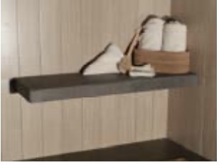
BETTER-BENCH ADJR Adjustable Bench
Installation Instructions
Notes:
BB-ADJR™ is designed for use in pre-tiled and post-tiled applications over UBC approved tile backing systems.
PLEASE READ ALL DIRECTIONS THOROUGHLY PRIOR TO THE INSTALLATION OF THIS UNIT!
BB-ADJR™ is suitable for mounting directly to the face of tile substrate (ultimate method), or after finish tile has been
installed. Wood blocking is not required unless INVISABOLT mounting supports are being used in the installation.
TO DETERMINE SUPPORT REQUIREMENT: Mounting wall to wall up to 36”: No additional support required
Mounting wall to wall up to 63”: One(1) BT-17S centered in span or Two(2) INVISABOLT supports
Mounting on back wall and one side wall up to 36”: One BT-17 S within 6” of open end or 2 INVISABOLT supports
Mounting along back wall and one side wall up to 63”: Three(3) INVISABOLT supports required
Mounting with no side support up to 36”: Two(2) INVISABOLT supports required
Mounting with no side support up to 48”: Three(3) INVISABOLT supports required
Mounting with no side support up to 63” max span: Four(4) INVISABOLT supports required
INVISABOLT™ SUPPORTS ARE NOT NEEDED WITHIN 6” OF A WALL MOUNTED CONNECTION
Placement Instructions
STEP 1 Turn BB-ADJR upside down and expand to desired width. Using a 1/4” metal bit, drill all similar sized holes through the exposed metal in the bottom, back and front face of the unit. Turn unit over and also drill through the exposed metal in the two 1/4” holes located in the bottom section and the 1/4” hole in the front face. Place the supplied corrosion resistant #12 x 1/2” round head machine screws through the |
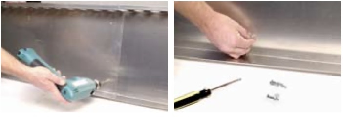 |
STEP 2If BT-17S is required for your installation, see those instructions prior to continuing. Install “Face Stiffener” in the center of BB-ADJR or |
|
STEP 3Determine pre tiled finish height, and location of bench and mark a horizontal line along back and side walls. For BT-17S(if required), locate edge or center line of BT-17S and mark a vertical line, make a mark on vertical line, 3” below horizontal line. Align upper corner of BT-17S on new mark and position on vertical line. Mark three (3) mounting holes on wall, and follow mounting instructions provided under BT-17S Installation. |
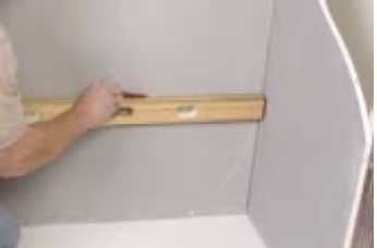 |
Standard Method (wall to wall/open ended)
STEP 1Position BB-ADJR at desired location and mark mounting holes of unit on substrate at all sides. Set unit aside. STEP 2Using a 1/4” masonry bit, drill marked locations completely through substrate. If wood backing or framing members are encountered, continue drilling backing using a suitable pilot bit which does not exceed 3/32” in diameter and use provided wood screws to secure bench. If hollow wall anchors are required in your installation, use a 3/8” masonry bit and drill completely through substrate. Insert the supplied hollow wall anchors into each hole and hand tighten the fastener to expand sleeve. Then remove screw for mounting bench or BT-17S. Be careful not to over-tighten the screws-snug is sufficient! Note: use of a power screw driver is not recommended. In some substrate, the sleeve portion of the fastener may spin while attempting to tighten. To prevent this, it may be necessary to grip sleeve flange with pliers or similar tool while first tightening fastener |
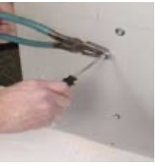 |
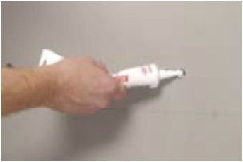
STEP 3Inject a small amount of caulk in each mounting hole and re-position BB-ADJR. Install all screws and secure BT-17S to BB-ADJR. Add additional caulk over screw heads and a continuous bead along top edge of bench where it abuts wall. |
 |
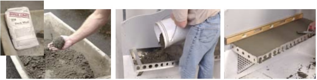
STEP 4Apply a stiff “deck mud” mortar (4 parts sand + 1 part Portland cement) to completely fill the BB-ADJR and BT-17S(if required in your installation). |
 |
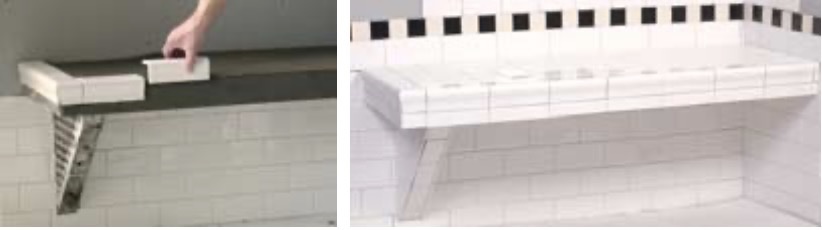
STEP 5Tile and grout the top, face and exposed sides of BB-ADJR and BT-17S as desired. |
 |
BT-17S™ Installation
BT-17S™ Installation Required if wall to wall span is greater than 36” or for open ended installation up to 36” max span. BT-17S is a modified version of the Better-Tray® and is intended to be mounted in a “Corbel” supporting condition.
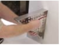
STEP 1Position BT-17S vertically with top edge at desired location and mark mounting holes on substrate or on tile. (3) locations |
 |
STEP 2Using a 3/8” masonry bit, drill marked locations completely through substrate. Note: If any structural wood members are encountered, it is necessary that you finish drilling with a suitable pilot bit which does not exceed 3/32”. |
STEP 3Place fastener sleeve in applicable drilled holes and hand tighten screws to expand sleeve. Remove screws and inject a small amount of caulk in each mounting hole, reposition BT-17S and re-secure mounting screws in sleeves. Add additional caulk over screw heads. |
|
STEP 4Re-position BB-ADJR, locate the two 1/4” holes in the top of the BT-17S, mark and drill through the bottom of the BB-ADJR and secure units together using the #12×1/2” machine screws and nuts provided. |
|
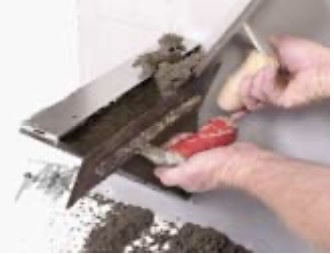
STEP 5Apply “dry pack” deck mortar to completely fill BT-17S, allowing mortar to press through the front holes. Screed even with side and front edges, brush off any excess mortar that protrudes through the multiple bonding holes on side of unit. Tile and grout as desired. |
 |
INVISABOLT™ Installation
Alternative self-supporting system for BB-ADJR
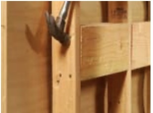
STEP 14×6 Minimum structural wood blocking must be installed flush to front face of studs prior to placement of tile substrate. Secure with (4) 16d nails at each end of block. Wood blocking must extend to the next wall stud beyond the installed BB-ADJR width, and centered at bench height. Install tile substrate according to manufacturer directions. |
 |
STEP 2Expand bench to width desired, being sure to keep large holes in front face of BB-ADJR aligned for both halves. Secure final dimension as detailed in placement instructions, Step A and C. Step B , “Face stiffener“ is not required with INVISABOLT system. |
|
STEP 3Viewing from front of bench, locate the 11/4” holes visible after expansion. These are the required mounting locations (drill out exposed metal if necessary). Place bench in final location and secure to wall using screws provided with BB-ADJR. Mark center point of 11/4” mounting holes and drill to a depth of 4” into pre-installed blocking using a 5/8” drill bit. Keep drill straight, level, and perpendicular to wall surface. Slide nylon insulator washer on INVISABOLT and tighten bolts until washer “just” makes uniform contact with front face of BB-ADJR. |
|
STEP 4Fill BB-ADJR with mortar as detailed above in Standard method Steps 2-4, and allow to cure at least 48 hrs. Tighten INVISABOLTS 1/4-1/2 turn or until resistance is about 15 lbs. torque. Do not over tighten or cause a deflection in face of bench. Finish top of bench, front face and ends as desired. |
 |